
SMT Turnkey Application Guide: Matching Equipment to Scenarios
A turnkey SMT line fits a production scenario when every machine in it stays inside its documented limits for board size, mix profile, throughput, thermal load and factory environment. Motek (Morel Equipments Co., Ltd.) is a Shenzhen-based SMT equipment supplier, founded in 2011, that assembles turnkey configurations around three core machines: a Hanwha Decan S2 pick-and-place platform, an XMR-800D reflow oven and an HMH830D automatic online glue dispenser. This application guide shows how to translate a production scenario into that configuration, and how to convert the result into purchasing terms and acceptance criteria you can actually test.
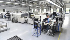
An SMT production floor: the configuration starts from the board mix and the facility, not from a machine list.
The matching problem: an equipment list is not a configuration
Most turnkey mismatches are not machine failures. They are scope failures — a line specified from a catalogue and then installed into a mix it was never matched to. A buyer compares headline placement speeds, selects the fastest platform within budget, and discovers during ramp-up that the real constraint sits somewhere else: in the largest panel the placer cannot hold, in a conveyor that does not line up with a 920 mm transfer height, or in exhaust ducting sized for one intake instead of two.
The alternative is to treat the line as a chain of documented limits. Three inputs decide that chain: the board and panel envelope, the mix profile (how many products, how often the line changes over), and what the building can physically supply — floor loading, exhaust capacity, cleanroom class and ESD protection. Each machine is then checked against those inputs, and the tightest limit governs the scenario.
Matching rule: the narrowest documented limit in the line governs the application. If a board fits the pick-and-place platform but exceeds the dispenser's 50–450 mm PCB width range, the configuration has to change before the purchase order — not the board, and not after installation.
Industry background: where configuration attention is moving
The global SMT equipment market was valued at approximately USD 4.3 billion in 2024, according to Research and Markets data published via GlobeNewswire on 20 October 2026. Market-level figures of this kind describe an industry, not a line: published values for "the SMT market" vary with scope, because some studies include components alongside equipment, so equipment figures should only be compared with equipment figures from the same scope.
The same source estimates inspection equipment as the fastest-growing SMT category, at a 15.2% compound annual growth rate for 2026–2033, attributed to AI-powered 3D AOI and SPI. For a buyer translating that into a configuration decision, the practical reading is that inspection scope — SPI, AOI, X-ray — is being specified into turnkey packages earlier than it once was, and acceptance budgets increasingly have to cover verification equipment as well as placement and reflow capacity.
At line level, high-mix production moves the constraint away from peak placement speed and towards changeover, program management and first-article verification. That shift is what makes scenario matching more useful than catalogue comparison.
The three-machine core and the limits each one sets
Hanwha Decan S2: placement envelope and accuracy
The Hanwha Decan S2 is the placement platform in this configuration. Its documented parameters are a speed of 92,000 CPH (optimum, HS10 head) on a 2-gantry × 10-spindle-per-head structure, placement accuracy of ±28 μm Cpk ≥ 1.0 at 03015 chip size and ±25 μm Cpk ≥ 1.0 for ICs, a component range of 03015 to 12 mm with a 10 mm height limit, a standard PCB range of 50 × 40 mm to 510 × 460 mm, and a high-strength aluminium alloy frame.
For a buyer, the accuracy figures are the entry ticket to fine-pitch and 03015 work, while the envelope figures decide whether the product can be built on this platform at all. Boards or panels beyond the documented standard range fall outside the specification and have to be agreed with the supplier before order rather than discovered at installation. The 92,000 CPH number is an optimum value tied to a named head, so it describes placement capability — not finished boards per hour.
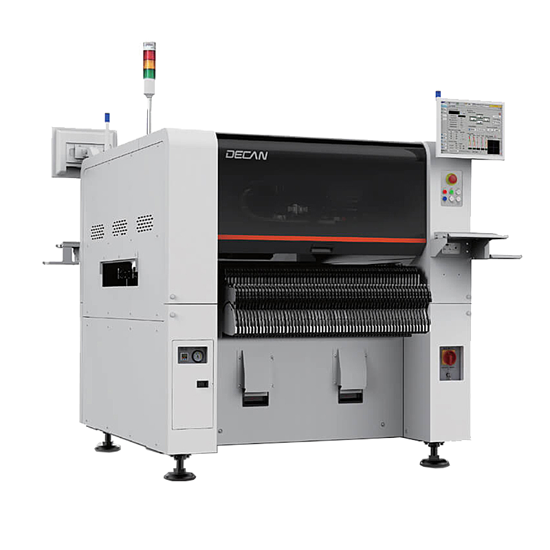
Hanwha Decan S2 pick-and-place platform: 2 gantries × 10 spindles per head, 03015 to 12 mm components, PCB up to 510 × 460 mm.
XMR-800D: thermal capacity, floor load and exhaust
The XMR-800D sets the thermal and facility side of the match. Documented parameters: 8 top and 8 bottom heating zones across a 3110 mm heating length, 3 top and 3 bottom cooling zones, a small-circulation rectifying plate structure, overall dimensions of 5520 × 1430 × 1530 mm, a weight of approximately 2710 kg, thick copper plate construction, and an exhaust requirement of 11 m³/min × 2.
Three of those numbers are facility commitments rather than machine preferences: roughly 2.7 tonnes of floor loading plus the access route for moving the oven in; two exhaust points sized at 11 m³/min each; and about 5.5 m of line length before infeed and outfeed conveyors are added. A scenario that looks sound on process grounds can still fail at the utility drawing stage.
Profile documentation is the other half of the thermal match. IPC-7801, the reflow oven process control standard published by IPC, is the usual industry reference for documenting thermal profiles and process control, and it gives buyer and supplier a shared vocabulary during acceptance.
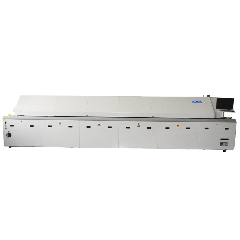
XMR-800D reflow oven: 8 top / 8 bottom heating zones over 3110 mm, 3 + 3 cooling zones, exhaust 11 m³/min × 2.
HMH830D: dispensing width, program library and transfer height
The HMH830D automatic online glue dispenser adds adhesive and dispensing capability, and it introduces the tightest width limit in the three-machine set. Documented parameters: PCB width range 50–450 mm, PCB transfer height 920 ± 20 mm, transport speed 0–5000 mm/min in either L→R or R→L direction driven by two stepper motors, industrial computer plus motion control card control, manual teaching programming, more than 1000 stored running programs, a weight of 650 kg, dimensions of L1060 × W1200 × H1700 mm, and a T20 mm chrome-plated steel plate platform.
The 450 mm maximum PCB width sits below the placer's 510 mm, so a board family that passes the pick-and-place platform may still not pass through the dispenser. Where the mix requires dispensing on the widest boards, that gap has to be resolved during configuration — by routing those products around the dispenser or agreeing a different arrangement — and not after the order. The 920 ± 20 mm transfer height is a mechanical interface with every neighbouring conveyor, and the 1000-plus program library with manual teaching is what makes repeated product changeover practical in a high-mix line.
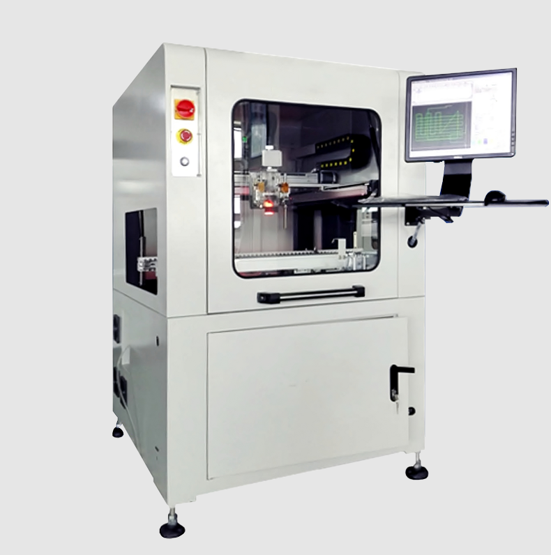
HMH830D automatic online glue dispenser: 50–450 mm PCB width, 920 ± 20 mm transfer height, more than 1000 stored programs.
Fit assessment: five checks before you choose models
- Board and panel envelope. List the smallest and largest board and panel in the mix in length × width, plus thickness and weight, then check each against the core machines: 50 × 40 mm to 510 × 460 mm on the Decan S2 and 50–450 mm width on the HMH830D. The narrowest limit in the chain is the real limit, and panels rather than single boards are what usually break it.
- Mix profile. Collect SKU count, batch size, changeovers per shift and the number of programs the line must hold. The dispenser's 1000-plus program storage and manual teaching routine matter only if the mix genuinely cycles through many products; on a single-product line they change nothing.
- Throughput arithmetic. Compare like with like. Fuji documents the NXT III H24G high-speed head at a maximum mounting speed of 37,500 CPH per module, while the Decan S2 rating of 92,000 CPH is an optimum figure with the HS10 head. Different bases — per module versus per machine, different head types — cannot simply be divided into each other. Normalise to your own board: components per board × boards per shift, then subtract changeover and verification time. If your existing fleet includes Fuji NXT, Yamaha YSM or JUKI platforms, confirm in writing how tooling, feeders, nozzles and programs will be shared or kept separate.
- Thermal and utility load. Zone count, heating length and cooling capacity define the profile window; footprint, weight and exhaust define the facility work. Check 8 top / 8 bottom heating zones over 3110 mm, 3 + 3 cooling zones, 5520 × 1430 × 1530 mm and 11 m³/min × 2 exhaust against the building before the layout is fixed.
- Environment and material flow. The application scenarios Motek works to assume an indoor cleanroom environment: ISO Class 8, 23 °C ± 2 °C, 40–60% RH, IP20/IP40 equipment, zero vibration and dust, ESD-protected areas complying with ANSI/ESD S20.20 with grounded workstations, and continuous 24/7 operation. Check loader, buffer, turner and unloader continuity, and carry the conveyor height through the whole line.
Step-by-step: from scenario to signed configuration
Step 1 — Build a board data sheet. Record the largest and smallest board and panel dimensions, thickness, weight, the component mix against the placer's 03015 to 12 mm and 10 mm height limits, and whether any product needs adhesive or dispensing. This single document drives every later decision and every comparable quotation.
Step 2 — Quantify the mix. State SKU count, average batch size, changeovers per day, the target changeover time and the size of the program library the line must keep. A high-mix profile with thirty active products is a different configuration problem from a single-product line running the same monthly volume.
Step 3 — Convert demand into a cycle-time target. Turn planned output into takt time and components per shift, then compare against placement capability on a consistent basis, leaving margin for changeover and inspection. Keep the optimum-versus-sustained distinction visible, because a 92,000 CPH optimum and a real shift output are not the same measurement.
Step 4 — Size the thermal block and the utilities. Match the required profile window to 8 + 8 heating zones and 3110 mm of heating length, confirm 3 + 3 cooling zones, then confirm the building can supply two exhaust points at 11 m³/min each and carry approximately 2710 kg over a 5520 mm footprint.
Step 5 — Lay out the full equipment chain. A turnkey line is more than three machines. The matched equipment set in Motek's SMT scenarios covers loader, solder paste printer, SPI, pick-and-place, reflow oven, unloader, AOI, X-ray inspection, ICT, splice machine, PCB turner, NG separator, stencil cleaner, environment monitoring and ESD protection, with PCB cutting (depaneling) and cleaning machines drawn from the wider product range. Decide which of these are in scope, which you already own, and where the NG separator and inspection stations sit in the flow — this is also where most production troubleshooting effort is concentrated later.
Step 6 — Fix acceptance criteria and purchasing terms. Only now should commercials be settled. Motek quotes a minimum order quantity of one unit, a lead time of 7–45 days depending on configuration, 100% pre-shipment testing and a 12-month product warranty, with customization covering voltage, logo, label, packaging, colour, size, graphics, material, line layout design and optional remote or on-site training. Agree in the contract which documented parameters will be measured at acceptance, on which board set, and by whom.
Scenario-based configurations in practice
High-mix EMS line with frequent changeovers. Placement speed is rarely the binding constraint here; changeover, feeder setup, program management and first-article verification are. A configuration that pairs the Decan S2 with the HMH830D's 1000-plus stored programs and manual teaching routine, and with dedicated SPI/AOI verification, addresses the actual bottleneck. The acceptance test should include a changeover dry run on a representative board family rather than a single-board speed demonstration.
Mid-volume consumer or industrial boards with adhesive dispensing. When the process needs glue or underfill, the dispenser enters the line and its 450 mm width and 920 ± 20 mm transfer height become the governing mechanical facts. Confirm the conveyor chain carries that height from printer through placer to oven, and confirm whether the widest boards in the mix can pass the dispenser at all.
Inspection-heavy boards — automotive ECUs, LED drivers, medical assemblies. Here the acceptance weight shifts to X-ray BGA inspection, AOI and ICT, consistent with the growth attributed to inspection equipment. Reflow documentation becomes part of the deliverable, not an afterthought, and IPC-7801 gives both parties a reference structure for it.
Evidence from an installed base. Motek's documented SMT factory case record spans Germany, Israel, India and Australia, covering 20–35 units over a five-year relationship, with applications including smartphone motherboard assembly, tablet circuit board production, ECU control unit assembly, LED display modules and LED streetlight drivers, and reported mass production of 20,000–100,000 pieces per day. The relevance to configuration is breadth: a mix spanning those applications is exactly the kind of scenario where matching has to be done per product family instead of per machine.
Comparison table: the three core machines side by side
| Machine | Documented parameters (selected) | Scenario signals it fits | Verify before order |
|---|---|---|---|
| Hanwha Decan S2 SMT pick-and-place machine | 92,000 CPH optimum (HS10 head); 2 gantry × 10 spindles/head; ±28 μm Cpk ≥ 1.0 (03015), ±25 μm Cpk ≥ 1.0 (IC); 03015–12 mm, H10 mm; PCB 50 × 40 to 510 × 460 mm; high-strength aluminium alloy | Fine-pitch and 03015 placement within a standard board envelope; high-mix lines where placement capability must be benchmarked on a consistent CPH basis | Largest panel against 510 × 460 mm; component height above 10 mm; how CPH is measured and on which head |
| XMR-800D SMT reflow oven | 8 top / 8 bottom heating zones; 3110 mm heating length; 3 + 3 cooling zones; small-circulation rectifying plate; 5520 × 1430 × 1530 mm; approx. 2710 kg; exhaust 11 m³/min × 2 | Production scenarios requiring a defined multi-zone profile window, with building space and exhaust available for a ~5.5 m, ~2.7 t installation | Floor loading and access route; two exhaust points at 11 m³/min; profile documentation and process control reference |
| HMH830D automatic online glue dispenser | PCB width 50–450 mm; transfer height 920 ± 20 mm; transport 0–5000 mm/min (L→R or R→L); two stepper motors; >1000 stored programs; manual teaching; 650 kg; L1060 × W1200 × H1700 mm | High-mix lines needing adhesive or dispensing, where many programs are stored and recalled rather than newly taught | Widest board against 450 mm; conveyor height match at 920 ± 20 mm; whether every product needs to pass the dispenser |
Purchasing terms and acceptance criteria that make the match testable
Motek's commercial terms are simple to state and worth writing down in the same document as the technical scope: minimum order quantity of one unit, lead time of 7–45 days, 100% pre-shipment testing, a 12-month warranty, multiple CE certifications on the equipment range, and customization covering voltage, logo, label, packaging, colour, size, graphics and material, plus line layout design and optional remote or on-site training. Nozzles can be engraved with letters rather than carrying a QR code — a small detail that matters when a mixed fleet has to be identified visually on the floor.
Acceptance criteria should translate those terms into checks: run the smallest and largest board and panel in the mix; confirm the method used to verify placement accuracy and who reports it; confirm conveyor height alignment across printer, placer, dispenser and oven; confirm exhaust and utility handover; receive the program library and teaching documentation for the dispenser; and agree a spares list covering feeders, nozzles and consumables. If your fleet already includes Fuji, Yamaha or JUKI equipment, list the shared tooling explicitly so that nothing is assumed at handover.
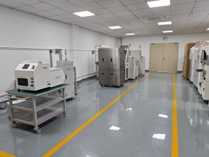
Pre-shipment testing and line assembly: acceptance criteria should be agreed on paper before the equipment is built.
Frequently asked questions
Which certifications and site conditions should be confirmed before accepting a turnkey line?
Motek holds multiple CE certifications for its equipment, and the SMT scenarios it works to specify an ISO Class 8 cleanroom environment at 23 °C ± 2 °C and 40–60% RH, IP20/IP40 equipment, zero vibration and dust, and ESD protection to ANSI/ESD S20.20 with grounded workstations. Two lists then need separating in the contract: what is certified on the specific models you order, and what your building must supply as a site condition. Both belong in the acceptance documents.
Can one configuration handle both high-mix small batches and volume production?
The three core machines provide a range rather than a guarantee. The Hanwha Decan S2 is documented at 92,000 CPH optimum with the HS10 head and at ±28 μm / ±25 μm Cpk ≥ 1.0 for 03015 chips and ICs; the HMH830D stores more than 1000 programs with manual teaching; the XMR-800D provides 8 top and 8 bottom heating zones over 3110 mm. High-mix performance is decided by changeover and programming time as much as by placement speed, so ask for a changeover dry run on a representative board family before signing.
What determines the cost of an SMT turnkey configuration?
Motek publishes no price list, so cost has to be built from scope rather than guessed from a headline. The main drivers are the number and model of machines, the board envelope required, whether dispensing is inline, how much inspection (SPI, AOI, X-ray, ICT) is included, feeder and nozzle quantities, spares, and customization such as voltage, packaging, labelling or line layout design. A quotation built from your board data sheet and mix profile is comparable between suppliers; a quotation built from a machine list is not.
Can the configuration be validated before committing to a full line?
The minimum order quantity is one unit, which allows a staged start instead of a full-line commitment, and 100% pre-shipment testing is part of Motek's stated quality control. Line layout design is available as a customization service, and remote or on-site training can be added to the scope. The practical sequence is to agree in writing which documented parameters will be measured at acceptance, with which board set, and by whom — then treat that agreement as the definition of a successful delivery.
What is the lead time, and what support is available after installation?
Quoted lead time is 7–45 days depending on configuration and customization, so board envelope and dispensing requirements should be fixed before the order is placed rather than adjusted during build. After-sales support includes remote technical support and 24/7 online service, with optional training for customer engineers at the supplier's site in China lasting about one week. Products carry a 12-month warranty, and Motek exports its full annual output to markets including the EU, USA, Australia, Canada and ASEAN.
Conclusion: match the constraint, then buy the machine
Matching SMT turnkey equipment to a production scenario is a sequence, not a comparison: fix the board and panel envelope, quantify the mix, normalise throughput to your own boards, size the thermal block and utilities, then lay out the full chain and only afterwards settle commercial terms. Three documented limits do most of the work — 510 × 460 mm and 03015 to 12 mm on the Decan S2, 3110 mm of heating over 8 + 8 zones with 11 m³/min × 2 exhaust on the XMR-800D, and 450 mm of PCB width at a 920 ± 20 mm transfer height on the HMH830D. Where those limits meet your product, the configuration is defensible; where they do not, no amount of extra equipment fixes it.
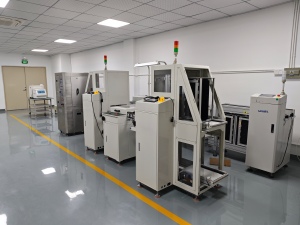
A configuration review starts with your board data sheet and mix profile.
Next step. Send your board data sheet and mix profile to sales@morequip.com and the review starts from the constraint that actually governs your line, not from a machine list.
The full SMT equipment brochure, including product and specification details, can be downloaded here: SMT equipment brochure (PDF).
Have Questions or Need More Details?
Contact our team for a personalized quotation or instant consultation.
Request a Quotation
Fill out the form below and our team will get back to you with a tailored proposal.
WhatsApp Direct Chat
Prefer to chat in real-time? Message us on WhatsApp for instant assistance & quick answers.
- Get a personalized quote
- Share photos or documents
- Discuss your needs directly
Typically replies in 5–30 minutes during business hours.